Sunday, November 19, 2017

Mounting the fenders, headlights, grill, & bumper

I wanted the fenders to be easily removable, with out tools.  I like to be able to sit on the front tires, and service the engine without bending over too much.
 Stainless steel quick release pins will do the job in place of the factory bolts.  They go right where the bolts used to be.  The tricky part is getting the pins something to anchor into other than the fiberglass.  Tether lines will keep the pins from getting lost.
 I made backing plates from 1/4" 6061 Aluminum.  These will spread the load over a larger area behind the fiberglass.  The plates have stainless steel receptacles for the quick release pins.
  More 3M panel bond secures the  backing plates to the back side of the fiberglass fenders.
Here I have a pin and a nut/bolt securing the plates until the epoxy dries.
 The rear of the fender is secured down low by small button activated fasteners from Quik-Latch.  Since this is a blind condition, Chris Brown made me some threaded mounting plates for the ball studs that I can adjust in and out.
 Quik-Latch offers buttons in different colors, so this red should be barely noticeable.
 The rear of the fender also uses at Quik-Latch fastener at the top.
The factory mounting tab to the left doesn't have anything to attach to on the chassis with all of the factory firewall sheet metal being removed due to the engine setback.
 I used 3/8" diameter DOM steel tubing to build "outlookers" to mount the factory head light buckets.  I had some 3" square tube fence posts laying around that I made mounting tabs from.
 It took 5 pieces of 3/8" tubing to make each side.  I chose 3/8" because that is the largest size my Woodward Fab 3 in 1 break/roller/shear would roll.
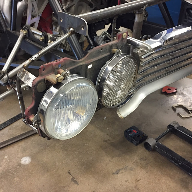
 Here the factory head light buckets are mounted to the outriggers.  The current plan is for the inner head lights to be engine air induction.  I've always though this looked mean.
The grill is reinforced in the center with 5/8" diameter DOM steel tubing.
The high beam hole in the factory head light bucket had to be enlarged to make room for the air inlet. The remaining headlight is a CIBIE with a flat front. The outer part of the grill is supported from the same two mounting points as the inside of the headlight bucket.
Looks pretty mean, especially with the 315 front tires trying to peek around.
The bumper is flimsy fiberglass, but will have load on it at high speeds, especially along the bottom edge, where a spoiler will be mounted. For mounts I used 3/8" steel tubing leading to 1/8" thick steel anchor plates, bonded to the fiberglass.  I wanted support spread all along the width of the bumper. It is four separate mounts that are detachable from the frame rails, and took 3 Saturdays to fabricate.
Bumper is mounted.  The center opening has been enlarged downward to match the bottom edge of the brake duct inlets.  An oil cooler will be mounted between the frame rails here, and should get plenty of air on a race track.

Saturday, November 11, 2017

Time to do some fab work on my own

With the progress of 2016 being painfully slow, I decided I would do some things myself.
 The last thing I had Chris at White Rino do for me was the exhaust.  We did it from 3" stainless steel, mandrel bend sections.  I did not want a cross over, to keep things simple under there, and hopefully to have a little more burble from the exhaust.  I wanted the exhaust to exit through the bumper, like at N-25 factory GS exhaust from 71/72.  This meant the exhaust had to come up into the trunk pan.  We had to cut into the freshly made trunk panels.
 This shows the challanges off getting the exhaust routed through the trunk area.  The mufflers are ahead of the axle, pointing upward.  They are small, short, stainless, straight through Magnaflows.  I want this car loud, since my other cars are fairly quiet cruisers.
 I brought the car home around March of 2017, and started seeing what needed to be done next.  I discovered that the footwell was too narrow for my size 14 shoes, and 3 pedals.  Here you can see where I cut and widened the footbox about 2" inches to the right, by tacking in a new piece of steel shaped to fit the rest of the floor pan in that area.
 Here you can see a new type of steering column mount that moved the column to a more comfortable position.
 Here is the back side of a new pedal mount bracket that Chris fabbed for me to hold the Wilwood brake/clutch pedal assembly.
 The new steering shaft position is just barely going to work.  Here is a bearing that will hold the shaft where it comes through the fire wall.
 A close up of a new pedal bracket.  The bolt is a temporary spacer.
 Titlton came out with a billet aluminum throttle pedal that compliments the Wilwood pedals well.  Here I am mocking it up right next to the brake pedal bracket. Clearance is tight!
My friend Mike Modena is in town from AZ, and is tweaking the steering column bracket.
 Gratuitous welding shot!
 His back is probably not going to be feeling good tomorrow.  He also had to remake two header tubes on the left side to clear the extra wide foot box.
 More welding that I don't trust myself doing.
 Mike got the steering and pedals 100% mounted and very stiff, so with him gone I am doing some easy stuff.  These are my rear bumper brackets.  The fiberglass rear bumper has no mounting holes, and I want it smooth with no carriage bolt heads showing.  This mounts will adhere to the back of the bumper with 3M panel bond epoxy.  I can't weld aluminum, so I making them from steel.  They are only 1/16" thick, so they are still very light.  That fiber glass can't take any abuse anyway, so there is no point in using heavy brackets to mount it to the frame.
 The small holes are for some 1/4" bolts that will hold the brackets to the bumper while the adhesive is curing.
 Oh yea, here is the finished steering column bracket with some cool supports that Mike suggested.  I ended up putting a 1/8" steel plate across the top of the bracket to create a four sided box with maximum strength.
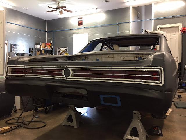
 Bumper is installed.  The blue tape shows where the exhaust tips will come through the bumper.  How about those cool, one year only, 65 factory tail lights?
 On to the front core support.  Do you know what this is?  A custom hood pin bracket that I made.
 In the background you can see a frame bracket for the core support that is removable via 2 bolts.  The foreground shows the vertical piece made from 1" steel tube.  Far left is the end of the horizontal piece that goes between the fenders.
 Here is the main part of the core support.  I call it that, but it will really only mount the headlights, grill, and upper part of the front bumper.  The radiator will be supported off the sway bar tube that is behind and below it.
 The stock, ugly core support in on the floor. Lots of measuring from it to replicate the factory mounting of the front components.
 Ah, the mysterious hood pin mount.
 Here is how it started.
 Here I am mocking up the hood pins, which are road race pieces from AeroCatch.
Can you see the pencil line where I thought about mounting them side ways?  I decided front to back would look better. It is now mid-summer of 2017.

A new year, more serious sheet metal fab

Now that most of the "bones" of the chassis are in place, it is time for more serious sheet metal fabrication.
 Here are the foot box, firewall, and driveshaft tunnel pieces.  Uh oh, looking a little rusty.  Surely things aren't starting to slow down, right?
 Trans tunnel has ended up as 3 pieces.
 Floor pans.
 Hmmm, it looks like a traditional 14" round air cleaner is not going to work.  The back of it clashes with the base of the windshield.  The motor is way back there.
 Rear firewall and wheel tubs and shaping up.  I wanted an interesting design in the bead roll work, and that is what I got.
 The fuel cell cage frame work is done, and is now being skinned with sheet metal.  Lots more bead rolling.
 Door panel design with the cage bars.
 Since I figured the car would be finished soon, I ordered my Rivals from Tire Rack.  Wise to order ahead of time since they are out of stock in the larger sizes most of the time.
 That is alot of rubber.
 Package tray is way cool.  We have something special in mind for the center section.
 These shock reservoir pass thrus were made by RideTech for one of their shop cars.  I saw them at a Good guys show, talked to them about them, and it turned out they had one more set.  I bought them.
 Everything in place.  Each pieces will be held in place by many 8-32 stainless steel button head screws.
 Starting to look like a real car.
The factory core support won't mate up to the new frame rails, so White Rino is making another one out of aluminum.  It looked too much like a stock piece, and not "racey" enough for me.  I had them stop work on this.  This post covers most of 2016.  Progress was slowing down.  Things need to change.  I am going to have to do some things myself to get them like I want them.